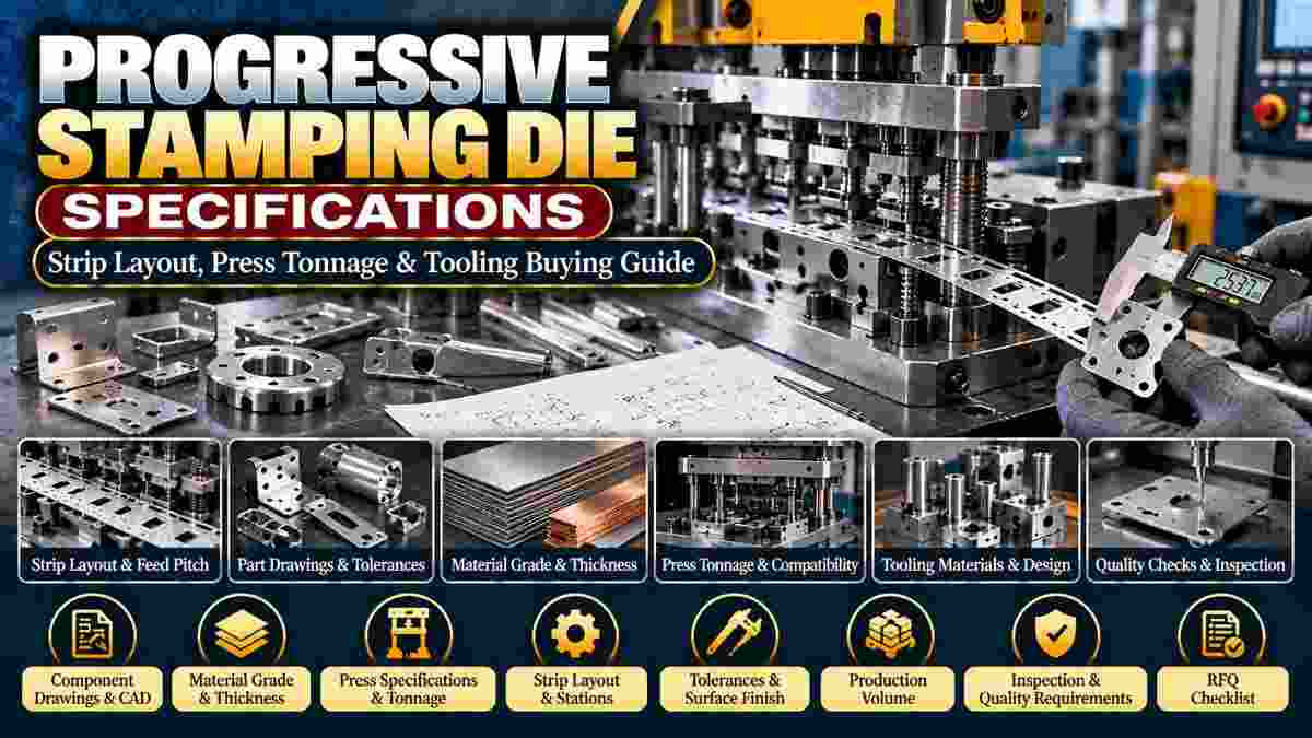
Are you planning to manufacture precision sheet metal components in high volumes? Ordering a progressive stamping die without complete technical information can lead to unsuitable tooling, production delays, and unexpected costs.
Progressive die design specifications should include component drawings, material grade, sheet thickness, production quantity, dimensional tolerances, press capacity, strip layout requirements, and inspection expectations.
Providing these details helps tooling manufacturers evaluate feasibility and develop an appropriate die design.
Parekh Wire Cut offers progressive dies and precision tooling solutions for industrial manufacturing.
A progressive stamping die is a multi-station tool that performs successive sheet metal cutting and forming operations as a strip advances through a stamping press.
Operations may include piercing, blanking, bending, embossing, and forming.
Common applications include:
Automotive components.
Electrical connectors.
Metal brackets.
Appliance components.
Industrial sheet metal parts.
Precision stamped components.
Explore Progressive Dies for product information.
Accurate specifications allow manufacturers to evaluate tooling requirements, material utilization, press compatibility, and component quality.
Incomplete information may lead to:
Incorrect material selection.
Unsuitable tooling dimensions.
Excessive material waste.
Incompatible press arrangements.
Dimensional problems.
Additional tooling modifications.
Approved drawings and production requirements should be established before finalizing the die design.
Provide detailed 2D drawings and 3D CAD models showing the finished component's geometry, dimensions, and functional requirements.
Useful information includes:
Overall dimensions.
Hole positions.
Bend angles.
Critical tolerances.
Datum references.
Edge conditions.
Surface finish.
Functional assembly requirements.
Clearly identify dimensions that are essential for component performance.
Material grade affects cutting forces, formability, springback, wear, and the tooling required to manufacture the part.
Common sheet materials include:
Mild steel.
Stainless steel.
Aluminum alloys.
Brass.
Copper.
Application-specific alloys.
Provide the applicable material standard, grade, temper, and supply condition.
Different materials may require different tool clearances and forming arrangements.
Sheet thickness influences cutting clearance, forming forces, bend characteristics, and tooling strength.
Specify:
Nominal thickness.
Permitted thickness variation.
Material grade.
Required finish.
Coil or sheet supply format.
Do not assume that one die can process multiple material thicknesses without engineering approval.
Strip layout is the planned arrangement of operations and component positions along the metal strip as it advances through the die.
It establishes:
Component orientation.
Strip width.
Feed direction.
Station sequence.
Carrier configuration.
Pilot positions.
Material utilization.
An effective layout balances production efficiency, component support, and tooling reliability.
Feed pitch is the distance the metal strip advances between consecutive press strokes.
The required pitch depends on component dimensions, strip layout, carrier design, and operation sequence.
Incorrect pitch can cause positioning errors, tool interference, or component defects.
The tooling manufacturer should determine the final feed pitch from the approved strip layout.
Press tonnage determines whether the available stamping press can safely perform the required cutting and forming operations.
Important factors include:
Material strength.
Sheet thickness.
Cutting perimeter.
Forming forces.
Stripping forces.
Operating conditions.
The available press must also satisfy energy, stroke, and loading requirements.
Press compatibility should be verified through engineering calculations.
Buyers should provide the available press specifications so the tooling manufacturer can verify compatibility.
Include:
Press type.
Rated capacity.
Bed dimensions.
Shut height.
Stroke length.
Operating speed.
Feed arrangement.
Bolster dimensions.
Available installation space.
The final die should be approved for the actual production press.
Dimensional tolerances should reflect the component's functional requirements and the capability of the selected manufacturing process.
Specify:
Critical dimensions.
Hole tolerances.
Position tolerances.
Flatness requirements.
Bend-angle tolerances.
Burr limitations.
Inspection methods.
Unnecessarily restrictive tolerances can increase tooling complexity and production costs.
Tooling materials are selected according to production volume, workpiece material, cutting loads, wear requirements, and maintenance expectations.
Common options include tool steels and suitable wear-resistant inserts.
Important factors include:
Hardness.
Toughness.
Wear resistance.
Heat treatment.
Machining requirements.
Maintenance access.
Final tooling materials should follow the approved die design.
Expected production volume influences tool construction, wear resistance, automation, maintenance planning, and overall project economics.
Provide:
Expected annual quantity.
Batch size.
Production frequency.
Estimated project life.
Future volume expectations.
High-volume projects may justify additional tooling features that improve repeatability and maintenance efficiency.
Progressive die acceptance should include checks confirming that trial parts meet approved drawings and agreed inspection requirements.
Potential checks include:
Dimensional inspection.
Visual inspection.
Burr evaluation.
Hole-position verification.
Forming accuracy.
Sample trial results.
Tool functionality.
Production consistency.
Agree on the acceptance criteria before manufacturing begins.
Progressive die prices depend on component complexity, material, number of stations, tooling materials, precision requirements, and expected production volume.
Major cost factors include:
Part geometry.
Die size.
Number of operations.
Tool steel requirements.
Precision machining.
Heat treatment.
Trial runs.
Inspection.
Customization.
Compare quotations using identical technical and commercial requirements.
A complete progressive die quotation request should describe the component, material, production equipment, quality requirements, and expected manufacturing volume.
Provide:
Finished component drawing.
3D CAD model, where available.
Sheet metal grade and thickness.
Critical dimensional tolerances.
Expected annual production volume.
Available press specifications.
Preferred feed arrangement.
Surface finish requirements.
Required inspection documentation.
Sample trial expectations.
Tool ownership and maintenance requirements.
Delivery schedule and project location.
Complete specifications help manufacturers prepare more reliable technical quotations.
Parekh Wire Cut offers progressive dies and precision machining services for industrial tooling applications.
Its website describes multi-station die manufacturing, CAD/CAM-supported development, CNC machining, Wire EDM, and customized tooling solutions.
Explore Progressive Dies for additional product information.
Confirm production capabilities, material specifications, manufacturing tolerances, and inspection arrangements before ordering.
Buyers commonly ask about production volume, tooling materials, feed pitch, customization, and quotations.
Yes. Progressive dies are commonly used for repetitive manufacturing of sheet metal components in suitable production volumes.
Yes. A single progressive die can incorporate several cutting and forming operations across different stations.
Yes. Strip layout determines the operation sequence, feed pitch, component positioning, and material utilization.
Yes. They are typically designed around specific component drawings and production requirements.
A detailed drawing is strongly recommended for accurate tooling evaluation and pricing.
You can request a progressive die quotation by sharing your component drawings, material specifications, production volume, press details, and quality requirements.
For new tooling projects, provide both the finished part drawing and the expected manufacturing conditions.
Explore Progressive Dies or contact Parekh Wire Cut to discuss your project and request a quotation.
Technical Note: Final progressive die design must follow approved engineering drawings, press specifications, material requirements, and verified tooling calculations.